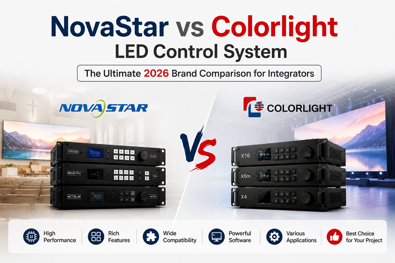
Setting up an LED display controller is the moment of truth for every installation. Get it right and the screen lights up perfectly. Get it wrong — wrong receiving card mapping, mismatched .rcfg file, incorrect port assignment — and you are looking at hours of troubleshooting while the client watches. This guide walks you through the complete setup process for both NovaStar (NovaLCT) and Colorlight (LEDVISION) controllers, side-by-side, so you can configure either brand with confidence.
At LEGIDATECH, every controller we ship comes pre-configured to your cabinet specs — but if you need to reconfigure in the field, or are setting up a controller from another source, this is the guide you need. All steps are verified against current software versions as of July 2026.
Software downloads referenced in this guide: NovaLCT from novastar.tech | LEDVISION from colorlightinside.com | LEDSCREENPARTS beginner guide | Linsn LED display installation reference.
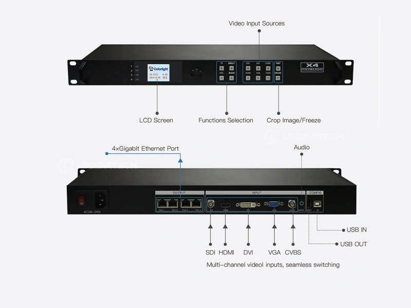
Pre-Installation Checklist: Before You Plug Anything In
| Item | NovaStar | Colorlight |
|---|---|---|
| Controller | MCTRL300/600/660/660Pro/4K or VX series | X1/X2/X4/X8m/X16/X20 |
| Receiving cards | MRV300-series (1 per cabinet typical) | 5A-75B/E or E320 (1 per cabinet typical) |
| PC requirements | Windows 10/11, USB port, NovaLCT installed | Windows 10/11, USB port, LEDVISION installed |
| USB cable | USB A-to-B (included factory-direct) | USB A-to-B (included factory-direct) |
| Ethernet cables | Cat5e/Cat6, solid copper (not CCA), 100m max | Cat5e/Cat6, solid copper (not CCA), 100m max |
| Video cable | DVI/HDMI/DP — match controller input | HDMI/DVI/SDI — match controller input |
| Power | AC 100-240V, 50/60Hz | AC 100-240V, 50/60Hz |
| .rcfg / config file | Module-specific .rcfg file (from module supplier or NovaLCT library) | Module config file (.rcfg) for LEDVISION |
| Cabinet layout diagram | Width × Height in cabinets; know your port assignments | Width × Height in cabinets; know your port assignments |
Critical prerequisites: (1) Know your total pixel count — multiply cabinets × pixels per cabinet. This must not exceed the controller’s rated pixel capacity. See our receiving card calculation guide. (2) Verify all receiving cards are the correct brand for your controller — mixing brands does not work. (3) Test all Ethernet cables with a cable tester before connecting — the #1 cause of setup failures is a bad cable.
Step 1: Hardware Connection — NovaStar & Colorlight
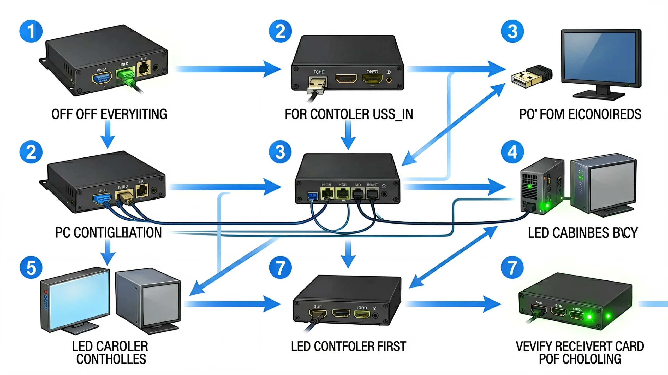
The physical connection sequence is identical for both brands. Follow these steps in order — skipping ahead causes detection failures.
- Power off everything. Controller, LED cabinets, and PC should all be powered off before connecting.
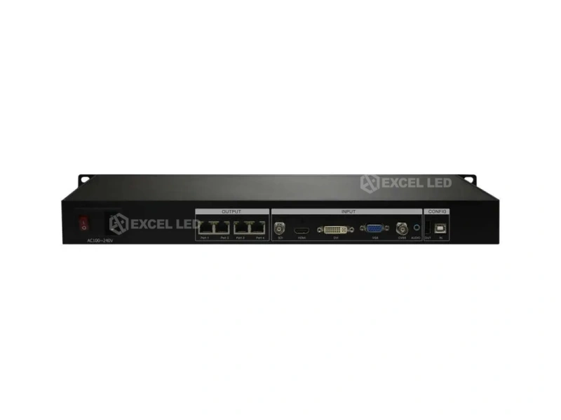
- Connect video source to controller input. HDMI for most setups. DVI for some NovaStar MCTRL models. SDI for broadcast. DP for 4K controllers (MCTRL4K, X16, X20).
- Connect USB cable from controller USB_IN to PC. This is the configuration link. Use the USB-B port on the controller (square connector).
- Run Ethernet cables from controller ports to receiving cards. Port 1 → Cabinet Row 1 (left to right). Port 2 → Cabinet Row 2. And so on. Label both ends of every cable.
- Daisy-chain receiving cards within each row. Receiving card OUT → next receiving card IN. The last card in each row does not connect to anything on its OUT port.
- Power on LED cabinets first, then controller, then PC. This sequence ensures receiving cards are ready when the controller sends its first signal.
- Verify receiving card indicator lights. A solid green LED on the receiving card means power is good. A blinking red LED means the card is waiting for signal — this is normal before configuration. No LED at all means check power.
Controller-specific notes: For NovaStar MCTRL660 Pro with fiber output — connect SFP+ modules before powering on. For Colorlight X16 — Genlock IN connection is optional for single-controller setups but required for multi-controller cascaded deployments. For full specifications, see our Colorlight X Series Full Lineup and NovaStar MCTRL Series Full Lineup.
Step 2: Software Installation & Controller Detection
NovaStar — NovaLCT
- Download NovaLCT from novastar.tech/downloads. Install with default options. Windows 10/11 recommended.
- Launch NovaLCT. On first launch, allow firewall access for both private and public networks.
- Connect USB cable from controller to PC. Windows will detect the device — wait for driver installation.
- In NovaLCT, go to Screen Configuration → Sender tab. The connected controller should appear automatically.
- If the controller does not appear: (a) Check USB cable is connected to USB_IN (not USB_OUT). (b) Verify controller is powered on (LCD or LEDs illuminated). (c) In NovaLCT, click Refresh or restart the software.
- Select the detected controller. The software will display: model name, firmware version, serial number, and port count.
Colorlight — LEDVISION
- Download LEDVISION from colorlightinside.com. Install with default options. Only Windows is supported — no macOS or Linux version.
- Launch LEDVISION. The interface language can be changed to English during installation or in Settings.
- Connect USB cable from controller USB_IN to PC.
- Navigate to Control → Screen Control.
- Click Detect Senders. The connected X Series controller should appear with its model name and port count.
- If no sender is detected: (a) Verify USB connection. (b) Check controller power. (c) Restart LEDVISION. (d) Try a different USB port on the PC — some USB 3.0 ports have compatibility issues; USB 2.0 is more reliable for configuration.
Step 3: Receiving Card Detection & .rcfg File Loading
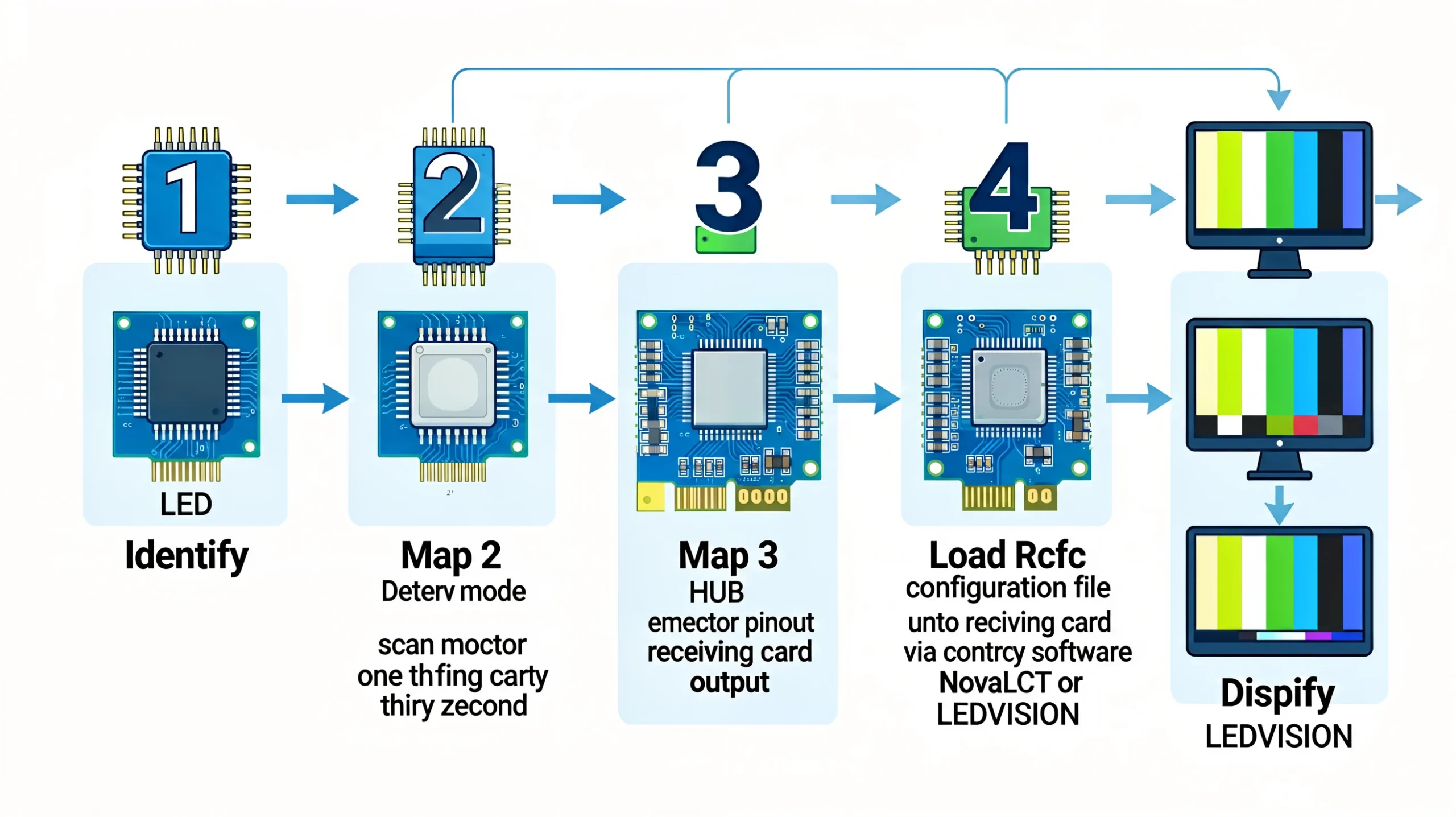
This is the most critical step — and where most configuration errors originate. The .rcfg (receiving card configuration) file tells the controller what kind of LED module is connected: pixel pitch, scan mode, driver IC type, data group arrangement, and refresh rate settings.
For NovaStar (NovaLCT):
- Select your controller in the Sender tab. Click Receiver tab.
- Click Detect Receiver Cards for each Ethernet port. NovaLCT scans the data line and identifies every connected receiving card by its ID.
- Verify the detected card count matches your physical installation. If you have 20 cabinets but NovaLCT finds 18, check cables on the 2 missing cabinets.
- Load the .rcfg file: In the Receiver tab, click Load Configuration File. Browse to your module’s .rcfg file (supplied by the LED module manufacturer or available in NovaLCT’s built-in library).
- Select all receiving cards (Ctrl+A) and click Send to Selected Receivers. This pushes the .rcfg to every card.
- If the .rcfg is wrong: The screen will show garbled images, wrong colors, or blank areas. Common symptoms: swapped red/blue channels (wrong data mapping), horizontal lines (wrong scan mode), or partial display (wrong resolution in .rcfg). Download the correct .rcfg from your module supplier — do not guess.
For Colorlight (LEDVISION):
- In the Screen Control window, after detecting the sender, click Detect Receiver Cards for Port 1. Repeat for each port.
- Each detected receiving card shows its ID, model, and status. Green = OK. Red = communication error.
- Load the .rcfg file: Click Screen Parameters. Click Load and select your .rcfg file. LEDVISION displays the module parameters: width, height, scan mode, data groups, and driver IC type.
- Click Send to push the configuration to all receiving cards.
- Colorlight 5A advantage: If you are using 5A-75B/E receiving cards, LEDVISION’s Intelligent Settings function can auto-detect the module configuration without a pre-built .rcfg file. Click Intelligent Settings → follow the on-screen wizard → the software auto-programs the receiving card by analyzing the connected module. This is particularly valuable for mixed-module fleets or when .rcfg files are unavailable. See the Colorlight Intelligent Settings tutorial for a complete walkthrough.
Step 4: Screen Mapping & Connection Layout
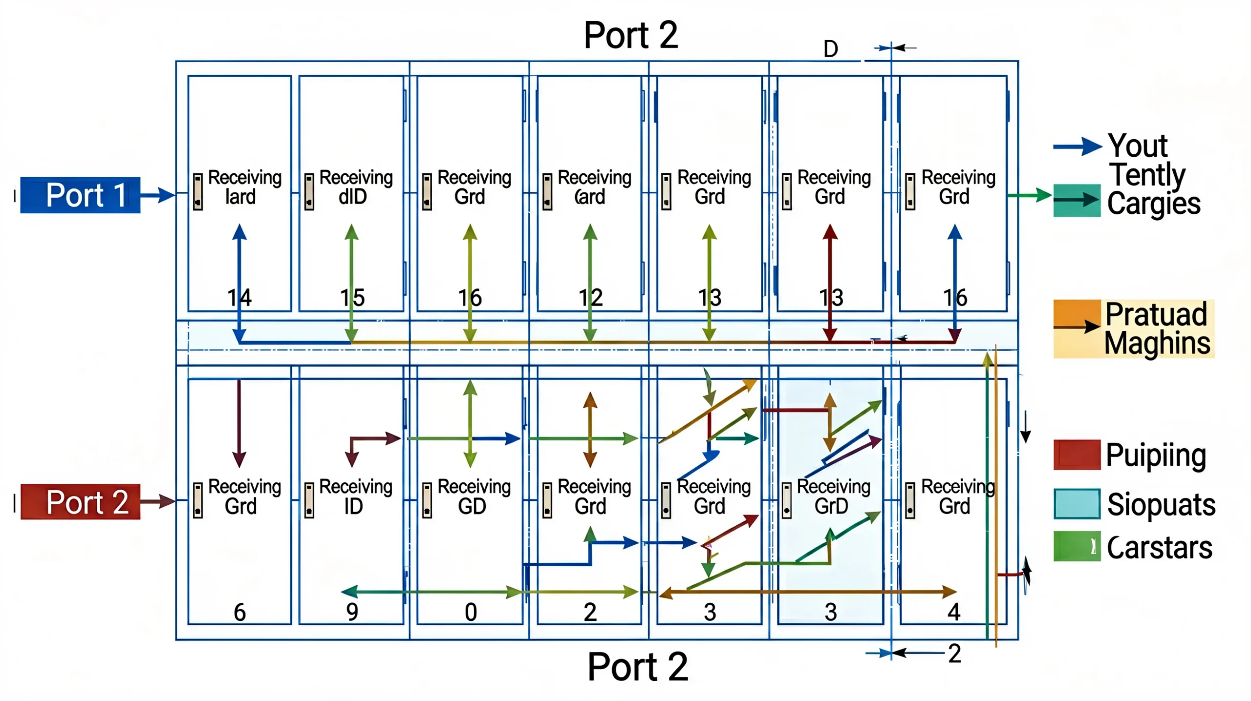
Screen mapping tells the controller which cabinet goes where in the physical LED wall. This is where you define the grid layout — how many cabinets wide, how many cabinets high, and which Ethernet port drives which section.
NovaStar NovaLCT Mapping:
- In the Receiver tab, after loading .rcfg files, click Connection.
- The Connection window shows a grid. Set the Row Count and Column Count for each Ethernet port based on your physical cabinet layout.
- Example: A 6m wide × 3m high P3.91 wall with 500×500mm cabinets = 12 cabinets wide × 6 cabinets high = 72 cabinets total. If using 2 Ethernet ports, each port drives 6 wide × 6 high = 36 cabinets.
- Connection Pattern: Choose Standard (left-to-right, top-to-bottom), Zigzag, or Custom based on your physical cabling. The default Standard pattern works for most installations.
- Click Send to Hardware. The screen should now display a test pattern or the connected video source.
Colorlight LEDVISION Mapping:
- After receiving card detection, go to Connection Mapping.
- Set the Row Count and Column Count per Ethernet port.
- LEDVISION provides a visual grid — drag cabinets to match your physical layout. The Connection Pattern tool auto-fills based on your selected topology (Standard, Zigzag, U-shape, Custom).
- For irregular layouts (e.g., L-shaped LED walls, door cutouts), use Manual Mapping to assign specific receiving card IDs to specific grid positions.
- Click Send to Receiver to deploy the mapping.
Pro tip for both brands: Always take a photo of your physical cabinet arrangement and Ethernet port assignments before starting configuration. When the software asks “Row Count for Port 2?” and you do not remember whether Port 2 drives the left or right section, that photo saves 20 minutes of trial and error.
Step 5: Output Settings & Video Input Configuration
With the screen mapped, configure how the controller processes the incoming video signal.
| Setting | NovaStar (NovaLCT) | Colorlight (LEDVISION) |
|---|---|---|
| Input Source | Screen Configuration → Output tab → select HDMI/DVI/DP | Screen Control → Output → select input port |
| Input Resolution | Set to match your source (e.g., 1920×1080) | Set to match your source |
| Scaling | Full screen / Pixel-to-pixel / Custom | Full screen / Custom scaling |
| EDID | Output → EDID → select resolution | Output → EDID → select resolution |
| Color Depth | 8-bit default; 10/12-bit on MCTRL4K/VX1000 | 8-bit default; 10/12-bit on X16/X20 |
| Genlock | MCTRL660 Pro / MCTRL4K: enable in Advanced | X8m / X16 / X20: enable in iSet or LEDVISION Advanced |
For broadcast setups with Genlock: Connect the external sync generator to the Genlock IN port. In NovaStar NovaLCT, enable Genlock under Screen Configuration → Advanced → Genlock. In Colorlight iSet (X16), enable under System Settings → Genlock → select External. Verify the Genlock indicator locks green before relying on the display for camera-facing content.
Step 6: Brightness, Color & Calibration
- Set target brightness: Indoor LED walls: 800-1,200 nits. Outdoor LED billboards: 5,000-8,000 nits. Rental/stage: 1,000-1,500 nits (lower for camera-facing). Adjust via NovaLCT’s Brightness slider or LEDVISION’s BRIGHT key on the controller front panel.
- Color temperature: Default is 6,500K (standard white). For broadcast, match to the studio’s color temperature (typically 5,600K or 6,500K). For retail/ambient, warmer temperatures (4,500-5,000K) may be preferred.
- Gamma: Default 2.2 for most applications. 2.4 for cinema/broadcast. Adjustable in both NovaLCT and LEDVISION.
- Pixel-level calibration (optional but recommended): Use NovaLCT’s calibration wizard with a supported colorimeter/spectrophotometer. LEDVISION supports calibration via compatible sensors. This corrects brightness and color uniformity across all cabinets — essential for fine-pitch indoor walls and camera-facing displays.
Step 7: Save, Backup & Deploy
- Save to receiver (both brands): Click “Save to Receiver” or “Save to Hardware.” This writes the configuration permanently to the receiving cards’ onboard memory. The controller will auto-load this configuration on every power-up — no PC needed for normal operation.
- Export backup file: NovaLCT: File → Export Configuration (.nlc file). LEDVISION: File → Export (.lvc file). Save to a USB drive stored in the controller rack. This is your disaster recovery plan.
- Test all inputs: Switch through every video input (HDMI, DVI, SDI, DP) and verify the display responds correctly. Do not assume the one input you tested works for all.
- Run for 30 minutes: Let the system run with content playing. Watch for: flickering (usually timing/refresh rate), color drift (thermal — normalizes after warm-up), or intermittent signal loss (Ethernet cable or receiving card issue).
Troubleshooting: Common Setup Issues & Quick Fixes
| Symptom | Likely Cause | Fix (Both Brands) |
|---|---|---|
| Controller not detected by software | USB cable in wrong port or driver issue | Check USB_IN (not USB_OUT). Try USB 2.0 port. Restart software. Reinstall driver. |
| Some cabinets black, others OK | Bad Ethernet cable or receiving card power | Swap Ethernet cable with a known working one. Check receiving card LED indicator. |
| Image garbled / wrong colors | Wrong .rcfg file loaded | Reload correct .rcfg from module supplier. Verify driver IC matches. |
| Screen flickering | Refresh rate mismatch or ground loop | Set refresh to 1920Hz min (3840Hz for camera). Check chassis ground connection. |
| Entire port section blank | Controller port mapping error | Verify port assignment in connection layout. Check port is enabled in software. |
| Horizontal lines across display | Scan mode mismatch in .rcfg | Re-download .rcfg. Verify scan mode (1/16, 1/32, etc.) matches module spec. |
| Color banding at low brightness | Grayscale processing not enabled | NovaStar: Enable “Better Gray” mode. Colorlight: Enable “Low-Brightness Grayscale.” |
| Genlock not locking | Sync signal mismatch | Verify Genlock source is bi-level or tri-level. Check BNC cable. Verify Genlock enabled in software. |
Brand-Specific Quick Reference
| Task | NovaStar (NovaLCT) | Colorlight (LEDVISION) |
|---|---|---|
| Download software | novastar.tech/downloads | colorlightinside.com |
| Detect controller | Screen Config → Sender tab → auto-detect | Control → Screen Control → Detect Senders |
| Detect receiving cards | Receiver tab → Detect Receiver Cards per port | Screen Control → Detect Receiver Cards per port |
| Load module config | Load Configuration File → Send to Receivers | Screen Parameters → Load .rcfg → Send |
| Screen mapping | Connection → set Row/Col → Send to Hardware | Connection Mapping → set Row/Col → Send |
| Brightness | Brightness slider in NovaLCT or front panel | BRIGHT key on front panel or LEDVISION slider |
| Save permanently | Save to Receiver | Save to Receiver |
| Export backup | File → Export (.nlc) | File → Export (.lvc) |
| Cloud platform | VNNOX (vnnovs.novastar.tech) | ColorCloud (cloud.colorlightinside.com) |
Frequently Asked Questions
Can I use the same .rcfg file for NovaStar and Colorlight?
No. NovaStar .rcfg files and Colorlight .rcfg files are not interchangeable. Each brand uses a proprietary format. You must obtain the .rcfg file specific to your controller brand from your LED module supplier. Most module manufacturers provide both versions. For more on brand compatibility, see our NovaStar vs Colorlight brand comparison.
How many receiving cards can one Ethernet port drive?
The limit is not the number of cards — it is the total pixel count on that port. For NovaStar MCTRL controllers: up to 655,360 pixels per port (at 8-bit color). For Colorlight X Series: up to 655,360 pixels per port. A P3.91 500×500mm cabinet (16,384 pixels) means max ~40 cabinets per port — but practical limits (cable length, signal integrity) typically cap at 20-25 cabinets per port. See our receiving card calculation guide for exact math.
Windows detects the controller but the software does not — what do I do?
This is almost always a driver issue. (1) In Windows Device Manager, check for unknown devices under “Universal Serial Bus controllers.” (2) Uninstall any unknown USB device, disconnect the controller, reconnect. (3) Reinstall NovaLCT or LEDVISION — the driver installs with the software. (4) Try a USB 2.0 port instead of USB 3.0 — some controllers have compatibility issues with USB 3.0 chipsets.
Can I configure the controller without a PC?
Partially. Both NovaStar and Colorlight controllers with front-panel LCDs (X2, X4, X16, MCTRL660 Pro, MCTRL4K) support basic functions without a PC: brightness adjustment, input source switching, display freeze/blackout, and preset recall. However, initial configuration (receiving card detection, .rcfg loading, screen mapping) always requires a PC with the brand-specific software. The Colorlight X4e uniquely supports standalone USB flash drive playback for digital signage — but still needs a PC for initial setup.
How do I update the controller firmware?
NovaStar: Download the latest firmware (.bin file) from novastar.tech. In NovaLCT, go to Settings → Hardware → Firmware Update. Select the .bin file. Do not power off during update (takes 2-3 minutes). Colorlight: Download firmware from colorlightinside.com. In LEDVISION, go to Settings → Device → Firmware Update. Same process — do not interrupt power.
What is the most common mistake when setting up an LED controller?
Loading the wrong .rcfg file. This causes garbled images, wrong colors, or blank screens — and the fix is always the same: obtain the correct .rcfg from your module supplier. The second most common mistake: poor-quality Ethernet cables (CCA — copper-clad aluminum — instead of solid copper). CCA cables cause intermittent signal loss that is extremely difficult to diagnose. Always use solid copper Cat5e/Cat6 cables. The third: powering on the controller before the LED cabinets, which can cause receiving cards to miss the initial handshake signal.
The Bottom Line
LED controller setup follows the same logical flow regardless of brand: connect hardware → detect controller → detect receiving cards → load .rcfg → map screen → configure output → calibrate → save → test. The software interfaces differ, but the underlying concepts are identical. Learn one brand well and the other takes 30 minutes to figure out.
The single biggest variable in setup time is not the controller brand — it is whether the controller arrives pre-configured to your cabinet specs. A factory-direct controller from LEGIDATECH with pre-loaded .rcfg files and tested port assignments can reduce on-site setup from 2-4 hours to 15-30 minutes. The time saved is more valuable than any hardware price difference.
Further reading from LEGIDATECH:
- Colorlight X Series Full Lineup 2026
- NovaStar MCTRL Series Full Lineup 2026
- NovaStar vs Colorlight: Ultimate 2026 Brand Comparison
- Colorlight Controller Price Guide 2026
- Receiving Card Calculation Guide
- NovaStar Controller Buyers Guide
Get Pre-Configured Controllers from LEGIDATECH
At LEGIDATECH, every NovaStar and Colorlight controller ships with 72-hour burn-in testing, firmware updated to latest version, .rcfg files pre-loaded to match your LED cabinets, and port assignments configured. Plug in and power on — no 4-hour setup session required.
- NovaStar controllers: MCTRL300 | MCTRL660 Pro | MCTRL4K | VX1000
- Colorlight controllers: X2 | X4 | X16
legidatechled@gmail.com | WhatsApp: +86 185 69492693
Published by LEGIDATECH — Your factory-direct source for NovaStar controllers, Colorlight controllers, LED display cabinets, and complete LED screen solutions. 15+ years of LED manufacturing experience. This guide references official software documentation from NovaStar and Colorlight, the LEDSCREENPARTS beginner guide, and Linsn LED installation reference.