


NovaStar VX1000 All-in-One LED Controller
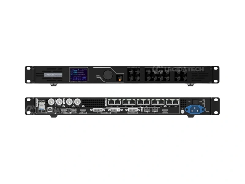
The novastar VX1000 integrates professional video processing and LED display control in a single 1U chassis. 6.5 million pixel capacity, 4K×1K@60Hz input, 10 Gigabit Ethernet ports, dual 10G fiber, Genlock, 3D — supplied factory-direct with 3-year warranty and pre-shipment burn-in testing from LED screen manufacturer Legida Tech.
What Is the NovaStar VX1000?
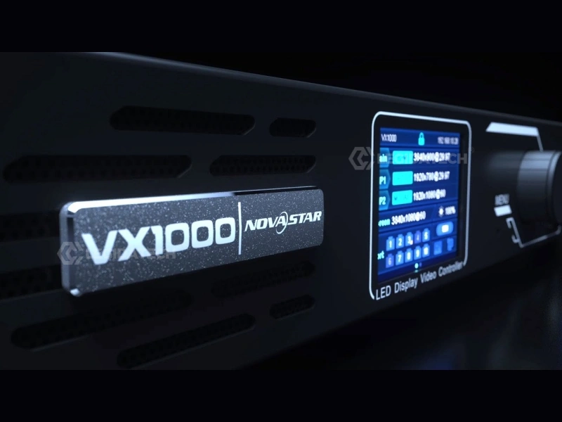
The VX1000 is NovaStar’s flagship all-in-one LED controller — it replaces the traditional two-box architecture of external video scaler plus independent sending card with a single FPGA-driven pipeline. Ten Gigabit Ethernet outputs, dual 10G SFP+ fiber ports, and three selectable operating modes make it the standard choice for medium to high-end rental, stage control, and fine-pitch LED applications.
All-in-One Architecture
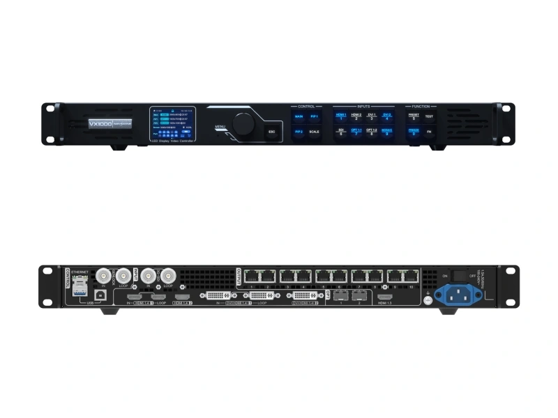
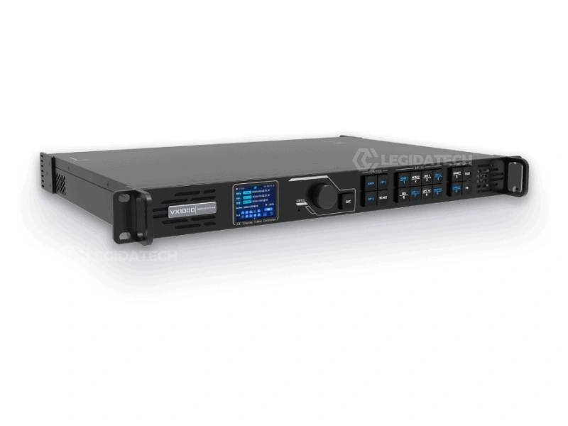
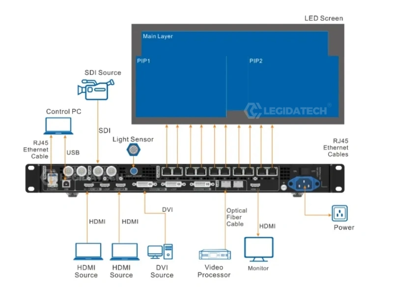
Video processor and sending card integrated in one 1U device — no separate sending card needed. Accepts HDMI 1.4, DVI, and 3G-SDI inputs; processes, scales, and distributes signal across 10 Ethernet ports directly to receiving cards. Eliminates approximately $800–$2,500 in standalone processor cost.
6.5 Million Pixels Capacity
Drives LED displays up to 10,240 × 8,192 pixels across 10 independent Gigabit Ethernet ports (650,000 pixels per port). Dual 10G SFP+ optical fiber ports enable lossless long-distance transmission up to 10 km over single-mode fiber — ideal for control-room-to-stage architectures.
Three Operating Modes
Video Controller for full-featured 3-layer composition. Fiber Converter for remote breakout over optical fiber up to 10 km. Bypass for ultra-low latency (~0.5 ms) in live camera and broadcast environments. Selectable via front-panel LCD or NovaLCT software.
Technical Specifications
Verified against NovaStar official firmware V1.4.0 and specifications document V1.6.0. All units undergo mandatory 24-hour burn-in testing at 80% port load before shipment from our facility.
| Parameter | Specification |
|---|---|
| Max Loading Capacity | 6.5 million pixels (10× 650,000 pixels per Ethernet port) |
| Max Output Width / Height | 10,240 × 8,192 pixels |
| Ethernet Outputs | 10× Gigabit RJ45 (NEUTRIK locking connectors, port redundancy supported) |
| Fiber Outputs | 2× 10G SFP+ Optical (OPT 1 self-adaptive input/output, OPT 2 for copy/backup) |
| Video Inputs | 2× HDMI 1.4 (with LOOP), 2× DVI (HDMI 1.4), 1× 3G-SDI (with LOOP), 1× OPT 1 |
| Max Input Resolution | 4K×1K@60Hz (3840×1080@60Hz) via HDMI 1.4 / DVI |
| Max Custom Resolution | Width up to 10,240 px; Height up to 8,192 px (mosaic input supported) |
| Layer Support | 3× 4K×1K independent layers (1 Main + 2 PIP), stepless scaling, free positioning |
| Genlock | IN + LOOP (BNC, 75Ω), bi-level and tri-level sync for broadcast frame accuracy |
| 3D Stereoscopic | Native support via EMT200 3D emitter and active shutter glasses (halves output capacity when active) |
| Low Latency | ~0.5 ms Bypass mode (~20 video lines) / ~16.7 ms Standard mode (1 frame at 60Hz) |
| Image Engine | SuperView III — stepless output scaling, input cropping, mosaic source composition |
| Presets | 10 user-defined presets with one-button recall via front panel or V-Can software |
| Input Backup | Auto-switchover within ≤0.5s; Ethernet port-to-port failover within ≤0.1s |
| Control Interfaces | 1× RJ45 Ethernet (PC control), 1× USB-A (PC), 1× USB-B (cascading up to 4 units) |
| Monitoring Output | 1× HDMI 1.3 (fixed 1920×1080@60Hz — do not manually override via Advanced Settings) |
| Software Ecosystem | NovaLCT V5.4.2+ (screen configuration) + V-Can (real-time control) + VICP (cloud monitoring) |
| Power Supply | 100–240V AC, 50/60Hz, 35W rated power consumption, 1.5A |
| Dimensions / Weight | 483.6 × 351.2 × 50.1 mm (1U rack-mount), 4.0 kg net |
| Operating Environment | 0°C to 45°C, 20%–90% RH (non-condensing), ≤45 dB(A) at 25°C ambient |
| Certifications | CE, FCC, IC, UL, CB, EAC, RCM, UKCA, NOM, KC |
Three Operating Modes for Every Deployment
Selectable via the front-panel LCD menu or NovaLCT software interface. Each mode determines the signal routing architecture and processing latency profile — choose based on your specific deployment requirements.
1. Video Controller Mode
The standard operating configuration with full video processing pipeline active: 3-layer composition (Main + PIP 1 + PIP 2), stepless output scaling, Genlock frame synchronization, and input source switching with auto-backup. Suitable for approximately 95% of professional applications — concert touring, stage rental, broadcast studios, fine-pitch commercial displays.
2. Fiber Converter Mode
Receives video data via OPT 1 optical input and distributes it through all 10 Ethernet ports to connected LED cabinets. Designed for long-distance architectures where the control room is 100m–10km from the LED wall. Use OPT 2 in Copy mode for dual-fiber transmission redundancy. Ideal for stadium perimeter displays and large-venue installations.
3. Bypass Mode
Pixel-to-pixel pass-through with minimal FPGA processing — latency drops to approximately 0.5 milliseconds (equivalent to 20 video lines at 60Hz). Only the Main layer is available; PIP layers are automatically disabled. Essential for live IMAG (Image Magnification) camera feeds, esports arenas, and real-time broadcast where frame-accurate timing is non-negotiable.
Key Features That Impact Real Deployments
Capabilities that directly affect system reliability, image quality, and total cost of ownership in professional LED display installations.
4K×1K@60Hz Native Input
Drives ultra-wide LED displays up to 10,240 pixels horizontally via HDMI 1.4 with HDCP 1.4 compliance. Mosaic input mode combines two DVI sources into a single wider canvas when one connector’s resolution bandwidth is insufficient — useful for non-standard aspect ratio displays.
Genlock Frame Synchronization
Bi-level and tri-level Genlock with IN + LOOP BNC terminals ensures frame-accurate sync with broadcast camera systems. Eliminates screen tearing and scan-line artifacts during live camera pans — a specific requirement in broadcast rights agreements for sports and entertainment venues.
3D Stereoscopic Output
Native stereoscopic 3D support via EMT200 3D emitter and compatible active shutter glasses. Primary applications: theme park attractions, simulation and training centers, premium cinema, and immersive brand experience venues. Note: 3D activation halves total pixel output capacity.
Triple-Layer Redundancy
Three independent failover mechanisms operating simultaneously: (1) Input source auto-switchover ≤0.5s, (2) Ethernet port-to-port backup ≤0.1s, (3) Device-level hot backup between cascaded VX1000 units. No visible interruption on screen during any single-point failure.
Pixel-Level Calibration
Per-pixel brightness and chroma correction executed in real time by the SuperView III image engine using calibration coefficients stored in receiving card memory. Eliminates external calibration processors — a key cost and complexity advantage in fine-pitch applications where LED binning variations are most visible.
NovaLCT + V-Can Software Suite
NovaLCT manages screen configuration, cabinet topology mapping, firmware updates, and .rcfgx file management. V-Can provides real-time layer positioning, input switching, brightness control, and synchronized preset recall across multiple VX1000 units via IP network.
How to Set Up the NovaStar VX1000
Standard 7-step configuration sequence validated against NovaStar firmware V1.4.0 and NovaLCT V5.4.2. Software downloads available via our NovaStar systems portal.
Hardware Connection
Connect video sources to HDMI 1.4 / DVI / 3G-SDI input ports on the rear panel. Run shielded Cat6A cables from the 10 RJ45 Ethernet output ports to the first receiving card in each cabinet chain. For cable runs exceeding 100 meters, deploy the 10G SFP+ optical fiber ports with single-mode fiber (OS2). Connect the VX1000 to your control PC via USB-B (recommended for initial setup) or RJ45 Ethernet. Configure Ethernet port backup pairs under Advanced Settings in NovaLCT for cable redundancy.
Install NovaLCT and Log In
Download and install NovaLCT V5.4.2 or later. Navigate to User → Advanced Synchronous System User Login to unlock the complete configuration toolset — without this step, several critical menus (including firmware update and advanced calibration) remain hidden. In Device Management, verify the VX1000 is detected and confirm its IP address on your control network.
Import Cabinet Configuration (RCFG/RCFGX)
If you have an RCFG or RCFGX file for your LED panels: Tools → Controller Cabinet Configuration File Import → Add Configuration File → select your file → Save the Change to HW. Without an RCFG file, use Quick Configuration: set cabinet row/column quantities and Port 1 Cabinet Qty. Critical constraint: total pixels assigned to any single Ethernet port must not exceed 650,000.
Send Configuration to Receiving Cards
Screen Configuration → Send RCFGx Files → select your configuration file → confirm transmission. The VX1000 automatically pushes configuration data to all receiving cards in the screen topology. After successful transmission, navigate to Screen Configuration → Save to RV Card to persist the configuration in receiving card non-volatile memory — prevents data loss after power cycling or controller replacement.
Set Input Resolution (EDID)
Input Settings → select active input source → EDID. Choose Standard or Custom resolution mode and match exactly to your video source output. A resolution mismatch will cause scaling artifacts and color space errors. Note: the 3G-SDI input auto-negotiates at 1920×1080@60Hz maximum and does not support manual EDID configuration.
Configure and Arrange Layers
Via front panel: press MAIN, PIP 1, or PIP 2 in the CONTROL area. Or navigate to Layer Settings in the LCD menu. Set Status to On → select input source → adjust size, position, and Z-order priority. Default state: only Main layer active, both PIP layers closed. When the Main layer uses a mosaic input source, PIP 1 and PIP 2 are automatically disabled.
Save Preset and Lock Panel
Save current state as a preset via the front panel PRESET button or V-Can — up to 10 user-defined presets. Press the SCALE button for one-click full-screen display. To lock the front panel against accidental input during live events: hold knob + ESC button simultaneously for 3 seconds. Repeat to unlock.
Configuration Video Walkthrough
Step-by-step NovaLCT configuration workflow for NovaStar VX1000 — demonstrated by Legida Tech engineering team.
After mastering the configuration readback workflow, proceed to map receiving cards in NovaLCT’s Screen Configuration module and verify Ethernet port assignments against your cabinet topology diagram. For advanced layer management, multi-controller Genlock synchronization, and custom EDID configuration, visit the NovaStar systems portal or contact our engineering team for direct one-on-one support.
VX1000 vs Alternative Controllers
The VX1000 eliminates the standalone video processor cost entirely — a net savings of $800–$2,500 for equivalent 4K processing capability compared to traditional two-box architectures requiring an external scaler plus independent sending card.
| Parameter | NovaStar VX1000 | Colorlight S4 | Linsn TS802D |
|---|---|---|---|
| Max Pixel Capacity | 6.5 Million | 2.3 Million | 2.6 Million |
| Ethernet Outputs | 10× Gigabit RJ45 | 4× Gigabit | 8× Gigabit |
| Max Input Resolution | 4K×1K@60Hz | 4K@30Hz | 1920×1200@60Hz |
| Fiber Output | 2× 10G SFP+ | Optional (external converter) | Not available |
| Genlock Sync | IN + LOOP (BNC) | Not available | Not available |
| 3D Stereoscopic | Native (EMT200) | Not available | Not available |
| Independent Layers | 3× 4K Layers | 2 Layers | 1 Layer |
| Input Auto-Backup | ≤0.5s Switchover | Manual only | Manual only |
| Software Ecosystem | NovaLCT + V-Can + VICP | LEDVISION | LEDStudio |
| Market Price (USD) | $1,800–$2,100 | $400–$600 | $300–$500 |
📩 Request VX1000 Competitive Quote →
Bundle with LED display cabinets for maximum savings — ask about volume pricing for 4+ units
Why Source Your VX1000 from LEGIDATECH?
Factory-direct procurement delivers measurable advantages in pricing transparency, pre-shipment quality assurance rigor, and post-sale engineering support responsiveness — benefits that marketplace resellers and drop-shippers cannot consistently match.
💰 Factory-Direct Pricing Advantage
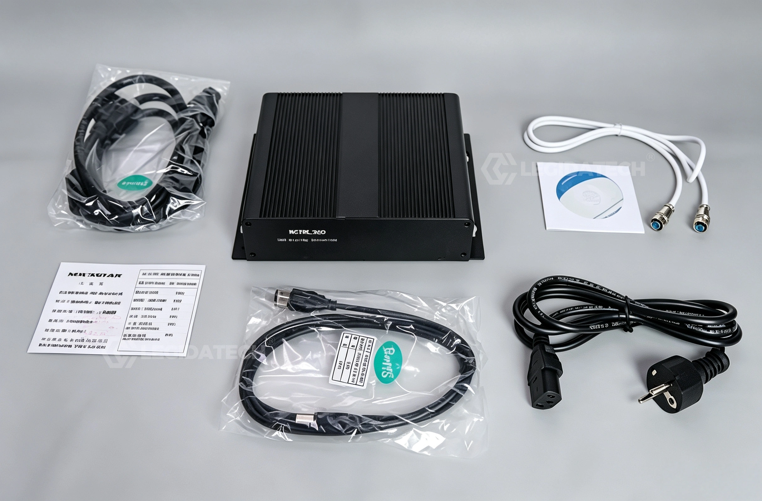
Distributor and reseller markups on NovaStar hardware typically range from 20–35%. As a volume NovaStar purchaser supplying complete LED display systems, Legida Tech offers near-wholesale pricing on individual VX1000 controllers — especially advantageous when procured alongside LED cabinets. For a representative stadium project requiring 4–8 VX1000 units, factory-direct procurement saves $3,000–$6,000 versus sourcing controllers and cabinets from separate vendors. Each unit includes the complete standard accessory package.
🔬 Pre-Shipment Burn-In Testing Protocol
Every VX1000 unit passes a mandatory 24-hour burn-in at 80% port load prior to shipment. Our QA protocol includes: Genlock loop verification with both bi-level and tri-level sync signals, 10G fiber BER (Bit Error Rate) testing at ≤10⁻¹² threshold, firmware version validation against the latest stable release, and full 10-port Ethernet output verification with known-good receiving cards. Units exhibiting any anomaly during burn-in are quarantined, root-caused, and re-tested after correction — a quality gate that most marketplace resellers skip entirely in favor of drop-ship speed.
🎓 Engineering Support Included
Unlike anonymous online resellers, you gain direct access to engineers who configure VX1000 controllers daily for real deployment scenarios. Support includes: custom EDID configuration files for non-standard display resolutions, optimized Ethernet port-to-cabinet mapping for complex topologies, firmware version rollback guidance, remote NovaLCT configuration review via screen sharing, and pre-deployment .rcfgx validation — all at no additional charge. Typical response time: under 4 hours during business hours (UTC+8, Monday–Saturday).
NovaStar VX Series Full Comparison
All four VX-series controllers share the same core FPGA-driven architecture — video processing plus LED control in one box, SuperView III image engine, and three selectable working modes. The differences come down to three factors: pixel capacity, layer count, and input resolution.
| Parameter | VX400 | VX600 | VX1000 | VX1000 Pro |
|---|---|---|---|---|
| Max Pixel Capacity | 2.6 Million | 3.9 Million | 6.5 Million | 6.5 Million |
| Ethernet Ports | 4× Gigabit | 6× Gigabit | 10× Gigabit | 10× Gigabit |
| Input Resolution | 1920×1080@60Hz | 1920×1080@60Hz | 4K×1K@60Hz | 4K×2K@60Hz (HDMI 2.0) |
| Layers | 1 Main + 1 PIP | 1 Main + 2 PIP | 1 Main + 2 PIP | Up to 6 configurable |
| User Presets | 10 | 10 | 10 | 256 |
| Genlock | — | — | IN + LOOP | IN + LOOP |
| 3D Support | — | — | Yes (EMT200) | Yes |
| Optical Fiber | 2× OPT | 2× OPT | 2× 10G SFP+ | 2× 10G SFP+ |
| Typical Application | Retail, conference | Mid-size rental | Rental, stage, fine-pitch | Broadcast, control rooms |
| Market Price (USD) | $400–$600 | $800–$1,200 | $1,800–$2,100 | $2,400–$2,700 |
Field Troubleshooting Reference
Common deployment issues encountered during VX1000 installation and live operation, with verified root cause analysis and resolution procedures developed from field experience.
| Symptom | Likely Root Cause | Verified Resolution |
|---|---|---|
| No signal output; LCD panel displays normal | Ethernet port mapping mismatch between NovaLCT configuration and physical cabling topology | Re-run Screen Configuration wizard in NovaLCT; verify port-to-cabinet mapping against physical wiring diagram; confirm receiving card status LEDs show link |
| Flickering or intermittent pixel rows | Damaged Ethernet cable, unshielded Cat5e cable, or Cat6 run exceeding 100-meter specification | Replace with shielded Cat6A cable (S/FTP); if run exceeds 100m, deploy 10G fiber link via OPT ports instead; verify RJ45 connectors are fully seated with locking tab intact |
| Color shift / pink tint across entire display | HDMI color space mismatch between video source output format and VX1000 EDID configuration | Verify input color space setting in V-Can (YCbCr vs RGB); re-export EDID from Input Settings menu; confirm source device output format matches EDID configuration |
| Genlock sync drift / rolling horizontal bars | Missing 75Ω BNC termination cap on Genlock LOOP output connector | Install 75Ω BNC terminator on Genlock LOOP when not actively daisy-chained to downstream device; verify sync source is delivering stable bi-level or tri-level signal |
| Firmware update stalls at 95% progress | USB data integrity error due to ground potential difference or AC power fluctuation during flash write | Connect control PC and VX1000 to same AC power phase; use USB-B direct connection (not Ethernet) for firmware updates; close all other NovaLCT/V-Can instances before starting |
| .rcfgx file fails to load (error on import) | Firmware version mismatch between the configuration file’s source controller and the target controller | Verify source and target firmware versions match exactly in Device Management; if versions differ, manually rebuild configuration or update firmware to match before importing |
| Single Ethernet port outputs no pixels | Port pixel overload (>650,000 px assigned) or physical cable break in receiving card chain | Check assigned pixel count per port in NovaLCT; physically verify RJ45 link LED at first unresponsive cabinet; test with known-good cable; reduce port load if exceeding 650,000 px limit |
Application Scenarios
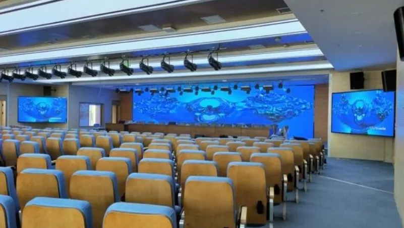
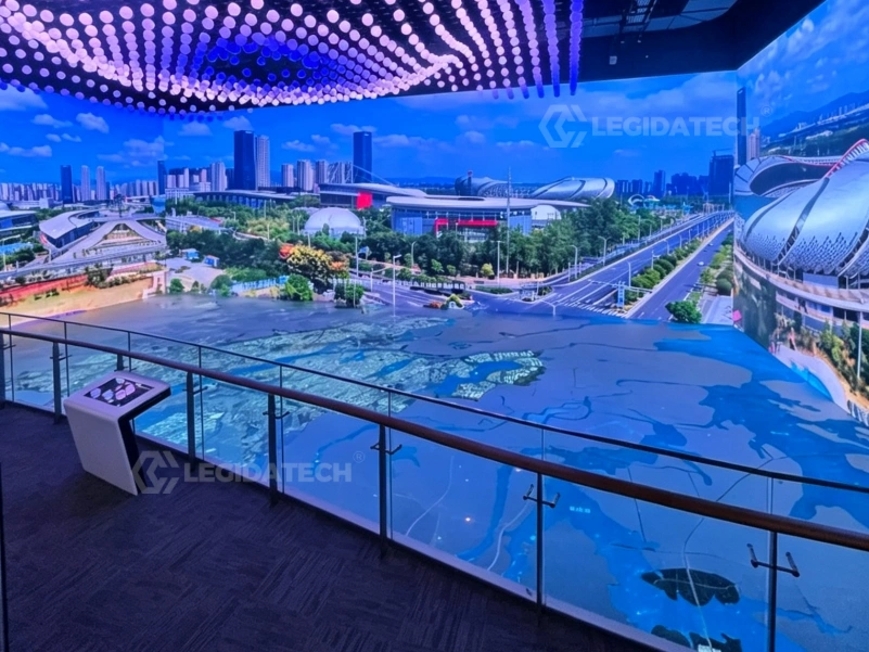
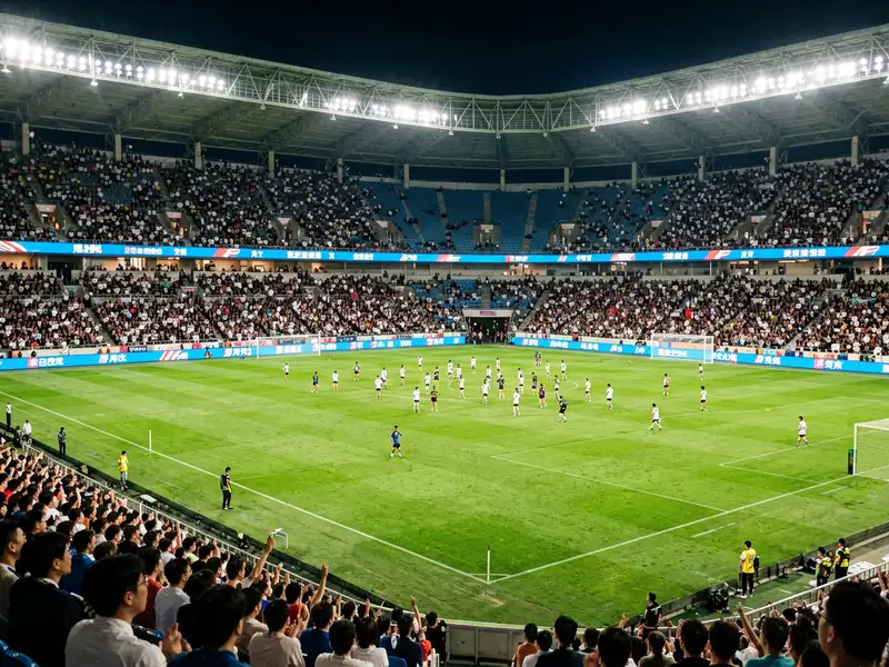
The VX1000’s combination of high pixel capacity, Genlock synchronization, and multi-mode operation makes it the preferred controller across diverse professional LED display applications.

Frequently Asked Questions
NovaStar VX1000 in Professional LED Display Systems — A Technical Deep Dive
The novastar VX1000 represents a significant architectural shift in LED display control systems — one that procurement engineers and system integrators should understand at the component level before specifying controllers for their projects. This technical analysis examines the VX1000’s FPGA pipeline architecture, fine-pitch integration methodology, redundancy design for live events, common cathode power efficiency, real-world stadium deployment patterns, and 8K future-proofing strategy, drawing on field data from installations across 30+ countries.
1. The FPGA-Driven All-in-One Architecture
To appreciate what the VX1000 achieves, it helps to understand the traditional two-box architecture it replaces. Until approximately 2019–2020, a standard LED display control rack required three discrete hardware components: an external video scaler ($800–$3,000 depending on input capability), an independent sending card ($200–$800), plus receiving cards mounted in each LED cabinet ($15–$40 per card). The scaler handled input format conversion, deinterlacing, and color space adjustment. The sending card repackaged the processed video stream into a proprietary protocol for transmission over Gigabit Ethernet to the receiving cards. Cumulative latency across this chain: 2–3 video frames (33–50 ms at 60Hz).
The VX1000 collapses the scaler and sending card into a single FPGA (Field-Programmable Gate Array) pipeline on one PCB, housed in a 1U rack-mountable chassis. The FPGA — running NovaStar’s proprietary SuperView III image processing firmware — handles input format detection, color space conversion, stepless scaling, layer composition, Genlock synchronization, and Ethernet packetization in a single pass. The result: end-to-end latency of approximately 0.5 ms in Bypass mode and 16.7 ms (one frame) in standard Video Controller mode. For live event engineers, this means one less device to rack, cable, power, and troubleshoot — a 5 kg weight saving and approximately 75% reduction in control rack space compared to the two-box equivalent.
The FPGA architecture also enables features that would require additional hardware in a discrete-component design: real-time per-pixel brightness and chroma calibration, three independent 4K×1K layers with stepless scaling, and input source auto-switchover within 0.5 seconds — all executed at line rate without frame buffer penalties.
2. Signal Processing Pipeline and Layer Composition
The VX1000’s SuperView III image engine implements a multi-stage processing pipeline that deserves closer examination. Stage 1 handles input acquisition: up to 6 physical inputs (2× HDMI 1.4, 2× DVI, 1× 3G-SDI, 1× OPT 1 self-adaptive) are digitized and synchronized. The 3G-SDI input is particularly valuable for live production environments — it carries embedded audio and supports cable runs up to 100m over RG6 coaxial cable, making it the preferred input for broadcast camera feeds.
Stage 2 performs color space conversion and deinterlacing. The engine detects the input colorimetry (Rec. 709, Rec. 2020, or sRGB) and converts to the display’s native gamut. Motion-adaptive deinterlacing is applied to interlaced SDI sources, preserving detail in moving areas while suppressing artifacts in static regions.
Stage 3 handles layer composition. Three independent 4K×1K layers — designated Main, PIP 1, and PIP 2 — can be freely scaled, positioned, and Z-prioritized. Each layer pulls from any input source, enabling configurations like: Main layer = presentation feed from HDMI 1, PIP 1 = live camera from 3G-SDI, PIP 2 = logo overlay from DVI. Layer transitions occur within the vertical blanking interval to prevent visible glitching during source switching.
Stage 4 is the output mapper, which partitions the composed framebuffer across the 10 Gigabit Ethernet ports according to the cabinet topology defined in NovaLCT. Each port carries up to 650,000 pixels using NovaStar’s proprietary NZP protocol, which embeds pixel data, clock recovery, and cabinet addressing in a single TCP/IP-friendly stream. The dual 10G SFP+ optical ports use an identical protocol over fiber, enabling lossless transmission up to 10 kilometers — critical for stadium deployments where the control room may be hundreds of meters from the nearest display segment.
3. Fine-Pitch LED Integration (P0.9–P2.5)
Fine-pitch LED displays (pixel pitch ≤ 2.5 mm) present unique control challenges that the VX1000 addresses through its high port count and integrated per-pixel calibration capability. Consider a P0.9 display using standard 600×337.5 mm cabinets: each cabinet contains 640×360 = 230,400 physical pixels. A single VX1000 driving 8 such cabinets serves 1,843,200 pixels — distributed across 4–5 Ethernet ports with significant headroom remaining for additional cabinets or higher refresh rate configurations.
The built-in pixel-level brightness and chroma calibration engine is particularly valuable in fine-pitch applications, where even minor LED binning variations become visible at close viewing distances (1.5–3 meters for P0.9–P1.5). The calibration pipeline applies per-LED correction coefficients stored in the receiving card’s non-volatile memory — data generated during factory calibration using spectrophotometric measurements of each individual LED. This eliminates the need for external calibration processors for most fine-pitch deployments, reducing system cost and simplifying the signal chain architecture.
For integrators working with COB (Chip-on-Board) fine-pitch displays, the VX1000’s calibration engine accommodates the unique thermal and electrical characteristics of COB packages, which differ from traditional SMD (Surface-Mount Device) LEDs in their voltage-current curves and thermal dissipation profiles. See our comprehensive guide on DIP, SMD, and COB LED display technologies for a detailed technical comparison of packaging types and their implications for control system selection.
4. Redundancy Architecture for Live Event Reliability
In live event production — concert touring, broadcast, corporate keynote presentations — display failure during a show is not an acceptable risk. The VX1000 implements a three-tier redundancy architecture that system designers should understand in detail to maximize deployment reliability.
Tier 1 — Input Source Backup: Any input connector can be designated as the backup for any other input. If the primary signal is lost (detected via loss of TMDS clock on HDMI/DVI or loss of carrier on SDI), the VX1000 automatically switches to the backup source within 0.5 seconds. The switch occurs at the next vertical blanking interval after signal loss confirmation (typically 2–3 frames of validation to prevent false triggering from momentary glitches). Both primary and backup sources must have matching resolution and timing parameters for seamless transition.
Tier 2 — Ethernet Port Redundancy: Each of the 10 Ethernet output ports can be paired with a redundant partner. In normal operation, both ports transmit identical pixel data. If a cable is severed, disconnected, or experiences excessive CRC errors, the receiving cards automatically switch to the redundant data stream within approximately 0.1 seconds — imperceptible to viewers. This topology requires dual Ethernet cable runs to each cabinet or cabinet group, which increases cabling cost by approximately 40–60% but provides essential protection for high-stakes live deployments.
Tier 3 — Device-Level Hot Backup: Two VX1000 units can operate in primary/backup configuration with fully synchronized state (input selection, layer configuration, preset status). The backup unit maintains an identical configuration and receives the same input signals in parallel. If the primary unit experiences hardware failure, the backup assumes control of the display. This configuration is recommended for broadcast and live event applications where any visible interruption is contractually unacceptable.
5. Common Cathode LED Efficiency and Power Economics
The VX1000’s grayscale timing engine interacts with LED driver technology in ways that directly impact operational power costs. Common cathode LED drivers — increasingly standard in new cabinet designs — supply red, green, and blue LEDs at their individually optimal forward voltages: approximately 2.0V for red, 3.2V for green, and 3.2V for blue. Traditional common anode drivers supply all three colors at a single voltage (typically 5.0V), forcing the red channel to dissipate excess voltage as waste heat.
The VX1000’s grayscale timing engine preserves per-color temporal characteristics regardless of the driver architecture, ensuring that the power efficiency gains of common cathode designs are fully realized in the final display output. In a representative 100 m² P3.91 outdoor display operating at 5,000 nits brightness: common cathode drivers with VX1000 control achieve 18–22% total power reduction compared to an equivalent common anode system. At an industrial electricity rate of $0.12/kWh and 12 hours of daily operation, this translates to annual savings of approximately $1,800–$2,400 — enough to recover the cost of the VX1000 controller itself within 12–14 months of operation.
This power efficiency benefit extends beyond direct electricity costs: lower power dissipation means reduced air conditioning load in indoor installations and extended LED junction life — a critical factor for B2B procurement managers evaluating total cost of ownership over a display system’s 5–8 year expected service life.
6. Stadium Deployment Case Study
A recent European stadium project illustrates the VX1000’s capabilities in large-scale, multi-controller deployments. The project scope: 200 m² of P10 perimeter display (4,800×72 pixels per side), two 80 m² P8 scoreboard displays (2,880×2,160 pixels each), and a 40 m² P5 entrance arch display (2,400×800 pixels) — 400 m² of total LED display area driven by 12 synchronized VX1000 controllers.
The perimeter displays were configured in a ring topology: each VX1000 drove one 50-meter segment (approximately 1.2 million pixels per controller, distributed across 6–7 Ethernet ports). All 12 controllers were Genlock-synchronized to the stadium’s broadcast camera system via the venue’s bi-level sync distribution infrastructure, eliminating camera pan tearing — a specific requirement stipulated in the venue’s broadcast rights agreement with multiple sports federations.
The scoreboard controllers operated in Fiber Converter mode: the control room, located 350 meters from the scoreboard structures, transmitted video over single-mode fiber to VX1000 units mounted in weatherproof enclosures directly behind each scoreboard. The 10G SFP+ optical links maintained bit error rates below 10⁻¹² over 8-hour continuous operation periods — well within the acceptable threshold for visually lossless digital transmission. Configuration cloning via .rcfgx files dramatically reduced setup time: the first perimeter controller was configured and validated in approximately 4 hours, with the remaining 11 controllers cloned and verified in under 2 hours total.
Total commissioning timeline: 3.5 days with a 3-engineer team. The Genlock sync infrastructure added approximately $1,200 to the control system budget (BNC distribution amplifiers and cabling) — a cost that the integrator described as “negligible compared to the value of passing broadcast technical inspection on the first attempt without any frame synchronization issues.”
7. 8K Readiness and Future-Proofing Strategy
Procurement decisions made today must account for the display resolution trajectory over a typical 5–8 year system lifecycle. The VX1000’s current HDMI 1.4 input supports 4K×1K@60Hz (3840×1080) — sufficient for the overwhelming majority of current professional LED deployments. However, as 8K content production and distribution infrastructure gradually matures, system designers should understand the VX1000’s upgrade pathways to avoid stranded capital investment.
For future 8K×1K (7680×1080) or true 8K×2K (7680×4320) requirements, the VX1000 offers two migration paths that do not require a complete control system replacement. Option 1: cascade two VX1000 units via Genlock synchronization, with each unit driving 4K×1K of the total raster. This approach leverages the existing 10× Ethernet port infrastructure per controller and is field-proven in the multi-controller stadium deployments discussed above. Option 2: upgrade individual controllers to the VX1000 Pro, which accepts 4K×2K@60Hz via HDMI 2.0 — a 4× increase in input bandwidth over the standard VX1000, enabling higher-resolution point-to-point display without multi-controller architectural complexity.
Critically, the 2× 10G SFP+ optical backbone on both the VX1000 and VX1000 Pro is already provisioned for beyond-4K bandwidth requirements. The fiber infrastructure — cabling, patch panels, and SFP+ transceivers — requires no physical upgrade to support future 8K workflows. Only the head-end controller hardware needs replacement or augmentation. This architectural decision by NovaStar’s engineering team provides meaningful capital expenditure future-proofing for venues and system integrators making controller investments today, as trenching, conduit, and cabling typically represent 40–60% of a permanent LED installation’s total control system cost.
The novastar VX1000 occupies a strategic position in the professional LED display controller market: it delivers broadcast-grade video processing, 6.5 million pixel driving capacity, and performance-critical features (Genlock, stereoscopic 3D, triple-layer redundancy) at a price point that eliminates the traditional scaler-plus-sender cost structure entirely. When procured through a factory-direct channel like LED screen manufacturer Legida Tech, the VX1000 becomes an even more compelling value proposition — pre-tested hardware with verified firmware, bundled pricing alongside LED display cabinets, and direct access to engineering support that understands the controller’s behavior in real-world deployment scenarios. For software downloads, firmware updates, and technical reference documentation, visit the NovaStar systems portal.
Ready to Deploy the VX1000 in Your Project?
Submit your screen dimensions for a custom factory-direct quotation with global delivery and engineering support.
legidatechled@gmail.com | +86 18569492693
Request Factory Quote
Fill out the form and our team will respond within 4 hours.