LED Screen for Broadcast & TV Studios: Pitch, Camera Sync & Panels
A studio LED wall can look perfect to the eye and fail on the camera feed. Moiré crawls across the wide shot, a dark band rolls through the anchor close-up, and the presenter’s face turns blue against a wall calibrated to D65. None of these faults show up in a datasheet. An LED screen for TV studio work has to be specified from the camera backward: the sensor, the shutter, the lighting, the signal chain and the panel all decide what leaves the building. This guide covers the pitch, sync and panel decisions that matter.
Short answer: An LED screen for TV studio use should run 7,680Hz refresh with genlock to the house reference, a matte COB or GOB surface, 1,000–1,500 nits of measured brightness and per-module calibration. Pixel pitch follows the camera, not the room: P1.5 is a common anchor-desk choice at 3–4 m, while wide shots at 6–8 m can use P1.8–P2.5. Test with the production camera before signing the purchase order.
What Is an LED Screen for TV Studio and What Changes On Camera?
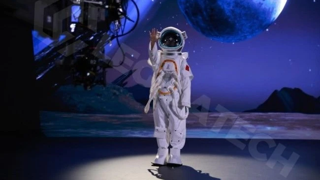
An LED screen for TV studio use is a direct-view LED wall specified for a camera as much as for the human eye. The electronics, surface and calibration are chosen for the sensor: high refresh, an external sync input, a matte face and measured color uniformity.
The camera exposes differences that a walk-through hides. Studio cameras run longer lenses, tighter crops and faster shutters. A wall that passes a phone check can still band on a 1/500s shutter or show a softbox reflection.
| Factor | Regular indoor LED | Broadcast LED |
|---|---|---|
| Refresh | 1,920–3,840Hz | 7,680Hz for fast shutters and 50/60fps |
| Frame sync | Free-running | Genlock to house reference |
| Surface | Glossy SMD common | Matte COB or GOB |
| Brightness | 600–1,000 nits | 1,000–1,500 nits under studio light |
| Calibration | Panel level | Module level, camera checked |
| Cooling | Fans acceptable | Passive or remote, for microphone silence |
The indoor LED screen range covers the cabinet hardware. The camera-facing decisions below are what turn it into a studio wall.
- Refresh and shutter match. The panel must refresh fast enough that the shutter always catches a complete frame, and the controller must lock to the camera clock.
- Matte surface, lower reflection. Studio lights hit the wall at shallow angles; a glossy face sends that light into the lens.
- Module-level color uniformity. A camera resolves module differences that the eye blends away.
- Low noise and low heat. Microphones pick up cooling fans, and a hot wall shifts its own color over a long day.
- Measured brightness, not peak claims. The useful figure is what the wall holds after calibration, with lights on and content playing.
Why Does an LED Screen for TV Studio Need Genlock and a 7,680Hz Refresh?
Genlock is a synchronization signal that locks the LED controller frame timing to an external reference, usually the broadcast house sync or a camera sync generator. Without genlock, the wall and the camera run on independent clocks. The sensor records two partial frames in one exposure, and the feed shows a tear line or a dark band that rolls through the shot.
Refresh rate reduces the chance of catching a partial frame; genlock removes the drift. At 7,680Hz, a 60fps camera frame contains about 128 refresh cycles, so any shutter position lands inside a complete image. At 3,840Hz, a 50/60fps camera usually works at conventional shutter angles, but fast shutters around 1/200s to 1/500s and narrow angles can still catch the transition (DOIT VISION, 2026).
Shutter angle connects the camera to the refresh figure. A 180° shutter at 25fps equals 1/50s; at 24fps it equals 1/48s; at 50fps it equals 1/100s. Sports, slow-motion and virtual production often use 90° or narrower, which doubles or quadruples the shutter speed and pushes the requirement toward 7,680Hz.
The controller should offer an external genlock input, not just an internal clock. Ask for the reference type the house uses: tri-level sync, black burst or PTP over IP. The LED display control system is where that input lives, and the LED display driver IC guide explains why low-brightness linearity matters once the wall is dimmed for a dark studio.
What Pixel Pitch Does an LED Screen for TV Studio Need by Shot and Distance?
Pixel pitch is the center-to-center distance between adjacent LED pixels, measured in millimeters. On camera, the visible result depends on the angular size of the pixel from the lens: pitch, camera distance and sensor resolution act together. A pitch chart alone cannot answer the question.
| Shot | Camera distance | Starting pitch | Note |
|---|---|---|---|
| Anchor close-up | 3–4 m | P1.5 | Common safe starting point |
| Mid shot | 4–6 m | P1.5–P1.8 | Test with the actual lens |
| Wide studio shot | 6–8 m | P1.8–P2.5 | Contrast matters more than pitch |
| Virtual set / XR | Stage dependent | P1.5–P2.6 | Tracking and volume size set the budget |
These ranges are starting points from supplier practice, not a guarantee. DOIT VISION (2026) recommends matching pitch to the specific camera, lens and distance, and notes that a P1.2 wall at 4 m and a P1.8 wall at 8 m can look comparable because angular resolution is what the sensor records. The reliable check is a camera test with your own body, lens and lighting.
Moiré is interference between the camera sensor grid and the LED pixel grid. A finer pitch, a softer lens, a longer distance, slight defocus and higher-contrast content reduce it, but it cannot be removed for every camera position. Anyone who promises a fixed percentage is guessing.
For virtual production, the LED screen for XR page covers the volume layout, and the EXR virtual production LED cabinet lists the P1.5–P2.6 range used on camera-facing stages. The camera-friendly LED screen for hybrid events guide applies the same pitch-versus-lens logic to events.
Which Panels Suit an LED Screen for TV Studio: SMD, COB or GOB?
SMD is a package in which each red, green and blue chip sits in its own surface-mount device on the module face. COB is a package in which the chips are bonded directly to the board and covered with a protective layer, producing a flatter, matte surface. GOB is an SMD module with a glue layer over the beads, which adds a protective matte coat.
| Package | Surface | On-camera behavior | Studio fit |
|---|---|---|---|
| SMD | Beads proud, often glossy | More specular reflection | Workable with matte coating and controlled light |
| COB | Flat, matte, sealed | Diffuse reflection, deep black | Best fit for lit studios and close cameras |
| GOB | Glue-filled SMD, semi-matte | Reduced glare, protected beads | Fit for stages and high-touch sets |
For a lit studio, the matte surface is the practical answer. A glossy wall can be bright enough and still lose contrast when a key light reflects into the lens. COB and GOB scatter the light instead of bouncing it back (DOIT VISION, 2026). The trade-off is repair method: COB modules are replaced as units, so the spare-parts plan matters.
Per-module calibration separates a broadcast wall from a bright wall. Ask for measured Delta E values per module, a uniformity report and a calibration file that can be re-applied after a module change. The MIP vs COB LED display comparison explains the packages at P1.5 and below, and the COB LED display modules and P1.25 COB LED display module pages show the hardware used in fine-pitch studio walls.
What Brightness, Color and Noise Specs Does a TV Studio LED Wall Need?
Brightness has to hold up against the lighting, not against a dark showroom. A broadcast studio typically runs 1,000–1,500 nits so the background keeps contrast when key and fill lights are on (DOIT VISION, 2026). A dark news set with low-key lighting can run 600–800 nits.
Color is a matching problem across three parts: the wall, the lighting and the camera. Studio lighting is often 3,200K tungsten or 5,600K daylight-balanced LED. An LED wall calibrated to D65 (6,500K) reads cool against tungsten unless the camera is white-balanced to the scene or the wall is adjusted to the lighting plan. Decide the white point with the lighting designer and the camera shader, then calibrate the wall to it.
For SDR broadcast, Rec.709 is the target. For HDR, HLG was developed by the BBC and NHK so one feed serves both SDR and HDR audiences, and it is the common choice for live broadcast (BBC and NHK, 2015). The HDR LED display guide covers metadata and calibration in detail. A broadcast wall should report measured P3 coverage and the curve it was calibrated to, not a generic wide-gamut claim.
Noise is the spec most studio buyers forget. Fans in the cabinets are audible on a boom mic, especially in a small set. Passive cooling, or power supplies moved to a remote equipment room, is the safer choice. Broadcast studios commonly target a background noise level around NC 15–25 under room-criteria practice (ANSI/ASA S12.2); ask for the sound pressure level at the operator position and measure it in the room.
How Does an LED Screen for TV Studio Fit ST 2110 Broadcast Workflows?
SMPTE ST 2110 is a suite of standards for carrying uncompressed video, audio and metadata as separate streams over a managed IP network. It replaces point-to-point SDI routing with a network fabric, and it uses PTP (IEEE 1588) for timing and NMOS (AMWA) for discovery and connection control. It is the direction most new broadcast facilities are building toward (SMPTE, 2026).
The LED wall is the last hop, not the network itself. ST 2110 terminates at a gateway, a media server or a processor that outputs SDI or HDMI to the LED controller. The practical question for the LED supplier is where that termination sits and what frame rate and color format it hands over. A 4K UHD ST 2110-20 stream at 10-bit 4:2:2 needs roughly 10 Gb/s of network capacity, so the broadcast integrator plans the fabric.
Redundancy follows the same logic. SMPTE ST 2022-7 sends duplicate streams over two paths and merges them at the receiver, so a single switch or cable failure does not blank the wall. On the LED side, ask for dual input paths to the controller and a defined behavior when one input drops. A clean changeover should not flash the wall, and the operator should see a status indicator rather than discover the failure on air.
If the studio is not on IP yet, the wall still needs an external reference and a clean SDI or HDMI handoff. The IP question changes the routing, not the camera-facing requirements: refresh, genlock, surface, color and noise remain the same. The LED video wall range covers the cabinet and controller side for both SDI and IP facilities.
What Does an LED Screen for TV Studio Cost and How Should You Budget?
Budget in four lines, not one. The panel is the largest line, but the controller and genlock hardware, the calibration work and the installation each carry a real share.
For the panel, the general indoor range at factory-direct level is about $350–$1,500/m² depending on pitch and package, and camera-facing fine pitch sits at the top. DOIT VISION (2026) publishes supplier reference figures of $800–$1,500/m² for P2.5, $1,500–$3,000/m² for P1.8, $2,500–$4,500/m² for P1.5 and $3,000–$6,000/m² for P1.2. Those are reference ranges, not a quote. Use the indoor LED screen price guide for a baseline and the LED screen price guide for the wider product picture.
A worked example: an 18 m² wall (6 m × 3 m) in P1.8 at $1,500–$3,000/m² is about $27,000–$54,000 for the panel. Add a genlock-capable controller, calibration, rigging and a spare-module kit. A virtual production volume adds camera tracking, render nodes and stage build; the virtual production LED wall cost guide covers that tier so this article does not double-count it.
Ask what is included: aging test, calibration report, on-site tuning days, spare modules at a stated percentage, and warranty terms for lamps and driver ICs. A low panel price with no calibration and no spares is the most expensive version of the project once the first module fails.
How Do You Test a Broadcast LED Wall Before You Buy?
Five tests take about ten minutes in a demo room and catch more than a forty-page datasheet (DOIT VISION, 2026). Run them with the camera and lens the production will use.
| Test | Method | Pass condition |
|---|---|---|
| Moiré | Camera at target distance, 30 seconds of moving content | No visible crawling pattern in playback |
| Genlock | Ask for the external sync input and its model | Named input, reference type, test footage |
| Refresh | 1/500s shutter, uniform field | No horizontal banding or flicker |
| Reflection | Studio lights on, camera pointed at the wall | Background keeps contrast and color |
| Noise | Quiet room, wall at working brightness | No audible fan or hum at the mic position |
Add a skin-tone test: put a presenter and a color chart in front of the wall and compare the playback against the reference monitor. Skin tone exposes calibration errors that a test pattern hides. For a multi-camera set, repeat the genlock and refresh tests with every camera, because one body can break the timing the others pass.
What Should an LED Screen for TV Studio Spec Sheet Include?
A spec sheet for a camera-facing wall should answer the questions a studio engineer will ask after the purchase order goes out.
| Field | What to request |
|---|---|
| Pixel pitch and native resolution | Measured wall size, module count and native pixel grid |
| Refresh and scan | Refresh at operating brightness, scan mode, grayscale bit depth |
| Frame sync | External genlock input, reference type, supported frame rates |
| Optical | Calibrated brightness, black level, white point, Delta E, viewing angle |
| Surface | Package type, matte or glossy, reflectivity under studio light |
| Thermal and acoustic | Average and maximum power per m², cooling method, sound pressure at operator position |
| Service | Front or rear access, module and power-supply spare ratio, calibration file backup |
| Delivery | Aging time, calibration report, on-site tuning days, warranty terms |
The Indoor HD small-spacing LED screen range is the hardware baseline for the P1.2–P2.5 studio walls described above.
Which Sources Support This LED Screen for TV Studio Guide?
Camera-facing differences, refresh guidance, moiré and reflection practice, and the five-test checklist: DOIT VISION, “LED Walls for Broadcast Studios: Solving Moiré, Refresh Rate & Focus Problems” (2026). IP media transport, timing and redundancy: SMPTE, ST 2110 suite and ST 2022-7 overview (2026); AMWA NMOS specifications. HDR broadcast format: BBC and NHK, HLG (2015); ITU-R BT.2100. Calibration practice: Legidatech, “COB LED Screen Calibration Site — Ehonor P1.5” (2024); CIE colorimetry. Panel and driver background: Legidatech MIP vs COB guide (2026) and LED display driver IC guide (2026). Price ranges: Legidatech indoor price guide (2026); DOIT VISION fine-pitch supplier reference ranges (2026).
Frequently Asked Questions About LED Screen for TV Studio
What refresh rate does an LED screen for TV studio need?
For professional broadcast cameras, 7,680Hz is the safe target. At 3,840Hz, a 50 or 60fps camera is usually workable at a 180 degree shutter, but 1/200s to 1/500s shutters can still catch a partial frame. The controller should also accept an external genlock reference. Test with the production camera and shutter.
Can a regular indoor LED wall be used in a TV studio?
It can look fine to the eye and still fail on camera. A standard indoor wall may lack an external sync input, use a glossy SMD surface, run 8-bit processing and use audible fans. A studio wall adds genlock, a matte COB or GOB surface, module-level calibration and low-noise cooling.
What pixel pitch is best for a news studio?
Match pitch to the shot and camera distance. P1.5 is a common start for an anchor desk at 3 to 4 meters, P1.5 to P1.8 for mid shots at 4 to 6 meters, and P1.8 to P2.5 for wide shots at 6 to 8 meters. A P1.2 wall at 4 meters and a P1.8 wall at 8 meters can look comparable. Test with your camera and lens.
Does an LED screen for TV studio always cause moiré?
Not always, but the risk is always present. Moiré is interference between the camera sensor grid and the LED pixel grid, and it cannot be removed for every camera position. A finer pitch, a longer distance, a softer lens, slight defocus and higher-contrast content reduce visibility. Verify with footage from the production camera.
What is genlock and do I need it for an LED wall?
Genlock locks the LED controller frame timing to an external reference such as the house sync or a camera sync generator. Without it, the wall and camera run on independent clocks, and a fast shutter can capture a tear line or rolling dark band. A high refresh rate helps but does not replace genlock in a live studio.
How much does an LED screen for TV studio cost?
Indoor panels at factory-direct level run about $350 to $1,500 per square meter depending on pitch and package, and camera-facing fine pitch sits at the top of that range. Supplier reference ranges are about $1,500 to $3,000 per square meter for P1.8 and $2,500 to $4,500 for P1.5. Add controller, genlock, calibration, rigging and spares.
Final Word: Is an LED Screen for TV Studio Right for Your Studio?
An LED screen for TV studio work is right when the wall is specified from the camera back: genlock and 7,680Hz for the shutter, a pitch that matches the shot, a matte COB or GOB surface for the lighting, module-level calibration for the color, and passive or remote cooling for the microphone. It is the wrong purchase when those items are treated as upgrades to a standard indoor wall and left out of the quote. As an LED screen manufacturer, Legidatech builds fine-pitch panels and can supply the module, control and calibration data behind the specification. The LED video wall range and the COB LED display modules pages show the hardware side.