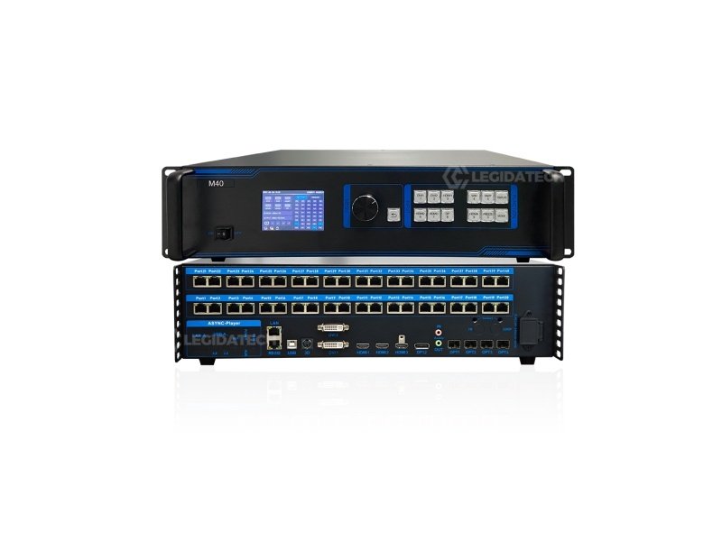
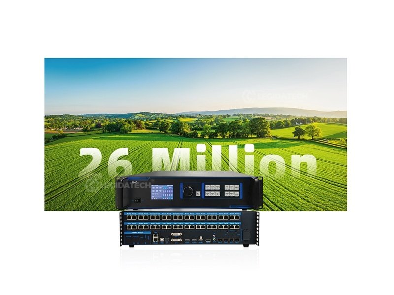
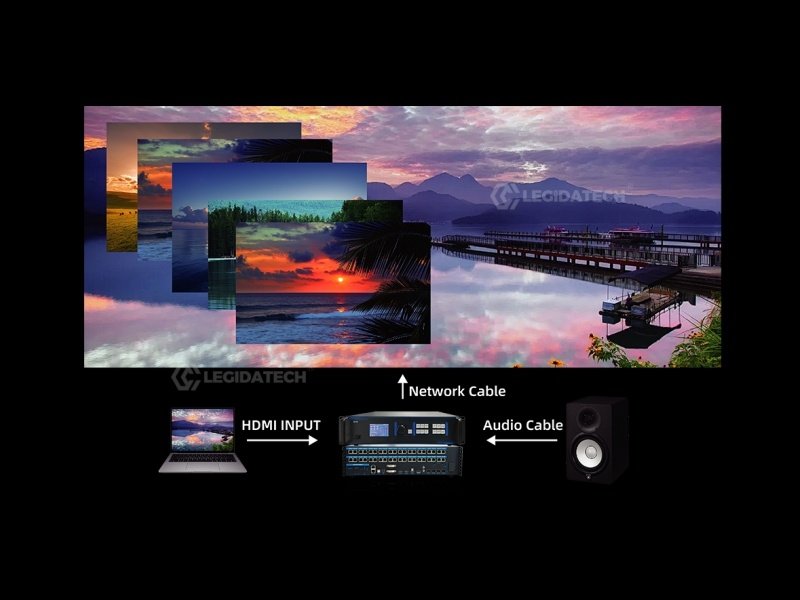
The M40 is the central nervous system between your video sources and your LED display. It receives up to six simultaneous inputs — cameras, media players, presentation laptops — processes them with real-time PIP multi-layer compositing, and drives your LED wall through 40 Gigabit Ethernet ports at up to 26 million pixels. No external switcher. No separate sending card. One device bridges the gap from source to screen.
From Source to Screen — One Device, Zero Compromise
Six independent inputs converge into the M40’s processing engine, then fan out across 40 Gigabit Ethernet ports — no external switcher, no separate sending card.
How the M40 Powers Your LED Display — Step by Step
The M40 sits at the center of your LED display system. Here’s the complete workflow — from plugging in sources to showtime.
1
Connect Video Sources
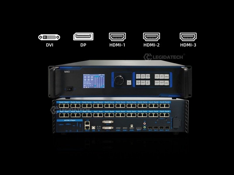
Plug in up to 6 video sources simultaneously — cameras (SDI via converter), media players, laptops, and presentation systems — into the HDMI 2.0, HDMI 1.4, DP 1.2, and DVI ports. The M40 auto-detects active signals with per-port LED indicators on the front panel.
2
Configure EDID & Output Routing
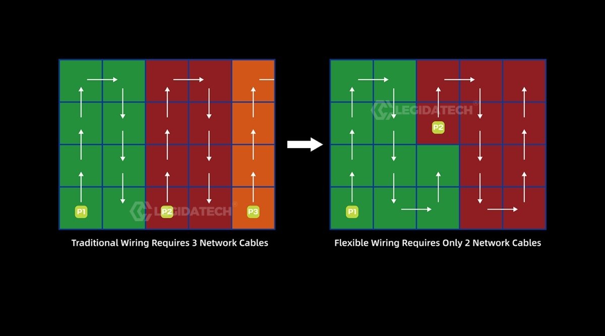
Set custom EDID profiles per input to ensure every source outputs at the optimal resolution for your LED wall. Map the M40’s 40 Gigabit Ethernet ports to your LED receiving cards — each port drives up to 655,360 pixels. Use fiber optic ports (OPT1-4) for long-distance runs to remote LED cabinets.
3
Arrange PIP Layout & Scene Presets
Open the PC control software — drag and drop each video source onto your LED canvas. Resize, crop, layer, and position up to 6 windows (2×4K + 2×2K). Save each layout as one of 128 scene templates. Set the built-in clock to auto-switch scenes on schedule, or trigger them via RS232 from your show controller.
4
The M40 Drives the LED Wall — No PC Needed
Once configured, the M40 runs independently. Video signals flow through the processor’s hardware pipeline — scaling, color correction, PIP compositing, and 3D/HDR processing happen in real time with sub-frame latency. The 40 Gigabit Ethernet ports transmit pixel data directly to LED receiving cards mounted on each cabinet, which drive the LED modules. The LED wall displays every pixel exactly as arranged — with zero tearing and frame-perfect sync across the entire canvas.
5
Operate — Front Panel, RS232, or Scheduled Auto-Run
During the show, operators use the hardware buttons (WIN, PART, FREEZE, MODE) for instant tactile control — no mouse, no menus. For automated venues, the scheduled scene switching handles transitions automatically. For integrated productions, RS232 serial commands from a lighting console or show controller trigger scenes programmatically. The M40 bridges your creative vision to your LED screen manufacturer’s hardware with zero friction.
The M40 in Your LED Display System
📹
Video Sources
Cameras · PCs · Players
→
⚙️
M40 Processor
PIP · Scale · Route · Sync
→
🔌
40× Eth Ports
Gigabit to Receiving Cards
→
🖥️
LED Video Wall
Up to 26M Pixels · 16K Wide
Engineered for Live Production
Every control is hardware. Every input is simultaneous. Every scene recalls in an instant.
Connect Anything
6-Channel Multi-Format Input — No External Switcher Needed
HDMI 2.0 (4K@60Hz), HDMI 1.4, DP 1.2, and dual DVI — all connected simultaneously. The M40 handles up to 5 active sources across 6 windows, replacing a standalone video switcher entirely. Custom EDID management ensures every source outputs at the optimal resolution for your LED wall.
Drag-and-drop each video source into position — resize, crop, and layer in real time. Window overlay, roaming, and seamless switching across 6 independent layers. PC control software with live preview ensures backstage content checking without affecting the main screen.
✓ Drag & Drop
✓ Live Preview
✓ 6 Layers Max
Automate Shows
128 Scene Templates with Scheduled Auto-Switching
Save 128 complete configurations — input routing, window positions, layer arrangements, and display settings for every moment of your show. The built-in clock triggers automatic transitions on schedule. For live events, recall any scene instantly via front-panel shortcut keys or RS232 from your lighting console.
✓ 128 Presets
✓ Scheduled Switching
✓ RS232 Control
Cinema Ready
Active 3D + HDR + Genlock — Broadcast-Grade Output
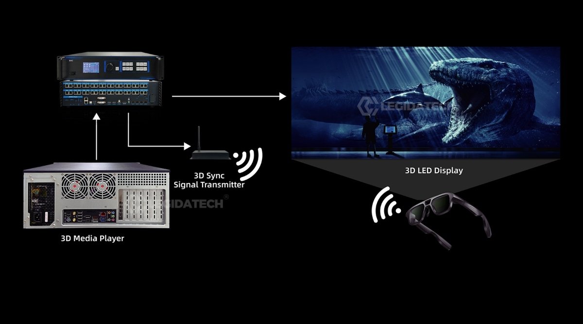
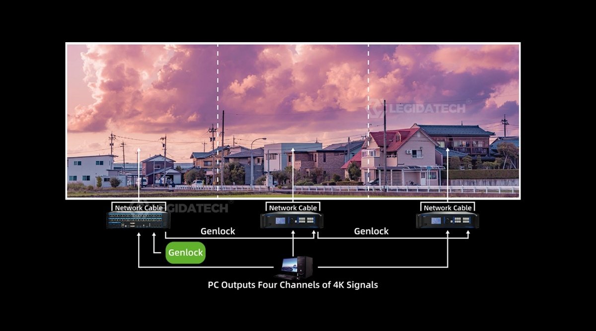
Active 3D via dedicated sync port with Mooncell emitter. HDR for expanded dynamic range. Optional Genlock ensures frame-level synchronization with broadcast cameras — critical for XR virtual production stages, live broadcast LED walls, and cinema-quality playback.
✓ Active 3D
✓ HDR
✓ Genlock Ready
Need help configuring your M40 input/output routing?
Our engineers pre-configure EDID profiles and scene templates before shipping.
A 2-in-1 device combines a video controller (input switching, PIP, scaling, color processing) and a sending card (Ethernet output to LED receiving cards) into one unit. One box replaces two — reducing latency, simplifying cabling, and lowering total system cost.
How many LED cabinets can one M40 drive?▾
The M40 supports up to 26 million pixels via 40 Gigabit Ethernet ports. Each port drives up to 655,360 pixels (~1280×512). For a typical P2.5 160×160-pixel cabinet, that’s approximately 1,000 cabinets. A single 4K wall (3840×2160 ≈ 8.3M pixels) uses roughly one third of the M40’s capacity — leaving room for multi-wall setups.
M40 vs MC-C2 — which one for my project?▾
The M40 is a hardware video processor with physical buttons — ideal for live events, broadcast, and stage use where instant tactile control matters. The MC-C2 is a full Windows server with C2 timeline software — better for pre-produced content, creative splicing, and permanent installations. Rule of thumb: live switching → M40. Timeline playback → MC-C2.
Does it need a separate sending card?▾
No — that’s the 2-in-1 advantage. The M40 has a built-in sending function with 40 Gigabit Ethernet outputs connecting directly to LED receiving cards. No external sender box required. This eliminates one device, one power supply, and one potential point of failure from your signal chain.
What cables and accessories are included?▾
Power cord, USB cable, DVI cable, HDMI 2.0 cable, DP cable, DP-to-HDMI adapter, and Certificate of Conformity — all in the box. Optical modules for the 4 fiber ports are sold separately.
Complete Your Control Rack
MC-C2 Multimedia Server
4U server with C2 timeline software for creative splicing and immersive displays.
HD-VP620 — 4K Huidu Processor
Alternative 6-port 4K processor for Huidu ecosystem projects.
HD-VP830 — Flagship 8-Port
Large-scale processor for stadiums and mega-events.
HD-C36C Async Control Card
For small standalone LED signs that don’t need a full processor.
How to Choose an LED Sending Card
Technical decision framework for LED display controllers.
LED Display Controller Setup Guide
Step-by-step hardware and software configuration tutorial.
Visit manufacturer page for latest firmware and documentation
Explore the Mooncell LED Control System Hub →Complete guide to the Mooncell LED control system — how processors, controllers and receiving cards work together, full product comparison, selection logic and applications.