
Today, I will explain the long-distance transmission scheme of LED display screen signals, mainly focusing on Nova’s photoelectric conversion equipment and Novastar’s control system.
And how to arrange system equipment and signal lines in different application scenarios.
The signals of the LED display screen control system are generally transmitted through network cables.
Due to the large venue and many devices, large venues are placed in a designated position, and the distance between the controller and the receiving card will be relatively far.
The transmission distance of a general network cable is about 80 meters.
If this transmission method is used, due to the attenuation or reflection of the signal during transmission, black screen, flashing screen and other faults may occur during playback.
In addition, the long distance between the video source and the controller or video processor is also a problem that needs to be solved.
The maximum transmission distance of ordinary DVI line is only 5m, and the transmission distance of HDMI line is about 30m.
When it exceeds this range, the signal will attenuate during transmission, causing the screen to flash screen, flash point and other faults during playback.
To sum up, in the large-scale event site, to solve the long-distance transmission problem, it is necessary to solve the signal attenuation problem caused by the two types of wires, that is, the network cable and the video cable are too long.
The usual treatment in the industry is as follows.
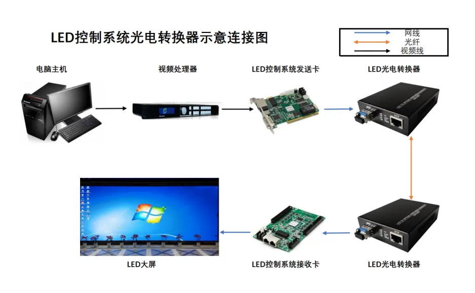
Use photoelectric converter to complete the long-distance transmission of network cable
The controller converts the image content to be displayed into an electrical signal, which is then transmitted to the photoelectric converter via a network cable.
The photoelectric converter converts the electrical signal into an optical signal, which is then transmitted over long distances via optical fiber.
Finally, the optical signal is transmitted to the receiving card via another photoelectric converter, and the image is finally displayed on the LED display.
![]()
1-1
The use of optical fiber video transmission to complete the long-distance transmission of video signals
The common fiber-optic video transmission architecture is shown in Figure 2-1.
Taking DVI signal transmission as an example, the video processor transmits the DVI signal to the DVI to fiber device, as shown in Figure 2-1.
After conversion, the DVI signal is converted into an optical signal and transmitted over long distances through optical fiber.
After that, the optical signal is converted into a DVI signal at the other end and transmitted to the controller.
After the controller processes the signal, it is transmitted to the receiving card, and finally the image is displayed on the LED display.
2-1
Optical fiber is used for long-distance transmission. The signal can be stably transmitted to the corresponding terminal by taking advantage of the strong anti-interference ability and long transmission distance of optical fiber during the transmission process.
Thereby meeting the scenario where the large screen is too far away from the device or signal source.
In addition, the characteristics of optical fiber transmission, such as wide bandwidth, large communication capacity and strong confidentiality, also enable the above two transmission schemes to be used in special environments.
Long-distance transmission scheme
However, for some important occasions or major projects, in order to avoid uncertainties such as equipment compatibility and reduce potential risks brought by different manufacturers and different hardware platforms.
In many cases, a complete set of solutions is needed, including long-distance transmission solutions.
3-1
For large event venues, this type of solution is obviously not the best choice.
In order to simplify the long-distance wiring of large venues and solve the problem of bloated system architecture, you can choose a model with a higher transmission rate.
For example, choose CVT10 and other models.
This is a 1 to 10 photoelectric converter, which can not only be used as a traditional photoelectric converter to meet the photoelectric conversion needs of 10 network ports, but also can be directly used with the sending card with integrated fiber optic interface.
The optical signal output by the sending card is directly converted into an electrical signal. The number of output network ports after conversion is determined according to the number of network ports corresponding to each fiber optic interface of the sending card.
3-1
3-2
For large LED display important projects, you can also choose a more professional product:
![]()
3-3
In addition to the Nova Nebula, various control system manufacturers have also developed related photoelectric conversion equipment.
H2F is similar to Nova Nebula CVT10.
You can use two devices to cooperate with the sending card, first convert the electrical signal output by the sending card into an optical signal for transmission, and then convert the optical signal into an electrical signal and output it to the receiving card.
Or you can directly receive the optical signal output by the sending card, convert it into an electrical signal and output it to the receiving card.